Command Classic/Build 1
The first Command Classic keyboard, built in summer 2020.
Background
At the time I decided to build this keyboard in June 2020, I was cycling between several off-the-shelf keyboards on umaru and tiring of their respective tradeoffs, while researching self-build techniques in fits and starts. In order to move on from this situation and have a proof of concept for my own ideas, I shelved the more challenging approaches in favor of designing something I could build right away.
Design
Two compromises made it possible to start building immediately. The first was handwiring the board. I had wanted to produce a PCB first to avoid the manual labor and do things cleanly from the start, but mastering the knowledge and the tools required to do so is a major time commitment for someone without a background in hardware.
The other was using a sandwich case. Designing a professional-looking enclosure involves 3D CAD software, but a sandwich constructed out of laser-cut sheets of material can be designed easily in two dimensions, without specialized software.
The keymap also features a small compromise with the keymap. I wanted to make something with a bottom row identical to the Macway JIS keyboards, but their 3.5U spacebars do not exist in the parts marketplace, or on any OEM keyboards with Cherry MX-compatible keycap mounts. In order to accomodate the 4.5U space bars used by some Japanese OEM keyboards, I eliminated the 英数 key.
Sourcing Parts: June 2020
Keycaps
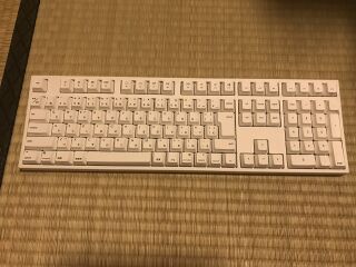
Given that I was handwiring and making a case using a common DIY technique, suitable keycaps were the only parts I expected trouble with. Group buys supporting JIS keymaps were just beginning to appear; at the time, ai03's SimpleJA that ran the previous year (and that I had missed) was the only one. ModernJA was expected to run at an indefinite point in the near future, but no appropriate keycap set was readily available.
I also needed a 4.5U space bar, which led me to look into using an OEM keyboard as a donor. Filco has the spacebar, but their pad-printed ABS caps are not very good relative to other options, only have Windows modifiers are available, and they are unrealistic to mix with other sets due to their idiosyncratic construction and taller profile than common cylindrical caps. Searching for OEM JIS keyboards with dye-sublimated PBT caps that would be pleasant, durable, and mix well with other sets, I landed on Varmilo and chose their "Mac" keyboard for its plain black-on-white design that wouldn't clash with generic caps from other sources.
Mixing keycaps was going to be necessary, because the Varmilo keyboard is really a Windows keymap with Mac-style legends printed on the caps. Fortunately, I was able to assemble a full set of modifiers from multiple kits of a traditional beige and gray IDOBAO set on aliexpress. The Command keys came from a matching set intended for Happy Hacking Keyboard clones.
For good measure, I added some accent purple keys from KPRepublic's "Muted" set. The legends on these keys were thicker and less sharp than the others, though, and they were later replaced with similar, tidier-looking caps from a garden-variety HKGaming set on the Amazon US store. Sets like these were not yet widespread or as cheap as they are now in 2020, or at least I did not notice them at the time.
Switches
I originally leaned toward using an MX Blue clone from Gateron or Kailh because I was familiar with that style of switch and liked it well enough, but I was beginning to hear good things about Kailh BOX Jade switches and their "click bar" construction, so I ordered a 9-key sampler from kbdfans containing several varieties of Kailh BOX, the common clicky Cherry MX variants, and Gateron's MX Blue clone.
I immediately worried that the BOX Jades were too "meaty" for me. I was already having problem with the similarly heavy Matias Click switches on my re-switched ADB keyboards, so while it was pleasant to press on the tester, I was wary of using it for the keyboard. The BOX White, though, identical save for its thinner click bar, had a lighter touch and seemed likely to work for me. After a few days of deliberation, I went back to kbdfans and ordered enough BOX White switches to furnish a keyboard.
Plates
After evaluating a few domestic (Japanese) and overseas options for price and ease of use, I decided to order the metal case components from LaserBoost in Barcelona. This consists of two 1.5mm-thick stainless steel plates with the same footprint - a solid one for the bottom, and one to house the keyswitches near the top. I chose to have them sandblasted to improve the appearance and texture of the parts that were to be visible.
Acrylic
My rudimentary design called for acrylic sheets stacked between the steel plates to create a hollow interior in typical sandwich fashion, and I wanted to place one more above the switch plate to frame up the key banks and make the end result look less raw and industrial.
Many US-based keyboard builders use Ponoko for acrylic components, but their shipping to Japan was expensive and I hoped to avoid them. If not for COVID-19, I might have visited some of the Tokyo-based operations in person, but their online ordering interfaces did not have the flexibility I needed. Ponoko also had a black glitter acrylic that I really wanted to use. I decided to postpone the decision on acrylic while I focused on getting the electrics working and building the bare minimum structure necessary to use it.
Controller
I had bought a Teensy++ 2.0 back in the winter of 2018, intending to do something along the lines of what I was now preparing to do, but it didn't happen and the board was still sitting idle, so I conveniently did not need to buy anything to use for a controller.
USB Port
I wanted a fixed USB port mounted on the back of the keyboard for a modular cable, but trying to mount the controller board flush with the edge of the case was not a good proposition. Any way I could think to do it would make the keyboard too thick, and require clearance in the opening for wires coming into through holes near the USB port.
To work around this, I ordered a Polulu USB Type C breakout board, which I could secure to the underlying acrylic sheet with nuts and screws, and which could have all of its wires connected in the rear.
Wiring
I ordered spools of wire from AdaFruit and a ribbon cable with clamp to connect the controller to the matrix, and diodes, from DigiKey.
First Build Phase: 21-25 July
The steel plates from LaserBoost arrived on 21 July, enabling me to mount switches and build in the core electrical components. This happened to be just ahead of a four-day weekend that the Japanese government had arranged for the (by then indefinitely postponed) 2020 Olympics, which also overlapped with KansasFest 2020 "Virtual Edition." The fortuitous timing allowed me to spend the better part of Thursday, Friday, and Saturday on the keyboard while mingling in KFest-related video chats.
Tuesday Night: Plates
With the plates in hand, I started out by attaching them to each other with tall nylon standoffs through the eight screw holes I had placed around the edges. My idea was that suspending the switch plate in midair over the base would make it easier to work with than if I had it laying directly on a work surface.
Wednesday Night: Mounting Switches
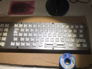
After extracting the space bar stabilizer from the donor keyboard, I installed it along with the remaining stabilizers and switches. Popping switches into the holes was easy, but I had not worked with Cherry-style stabilizers before, so I took my time ensuring that they were mounted properly and that they could move freely. After the switches were mounted, I flipped the switch plate over, reattached it to the standoffs, and began bending and placing diodes on the switch posts before breaking for the night. The switch plate remained in this upside-down configuration until the wiring was complete.
Thursday: Matrix
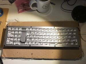
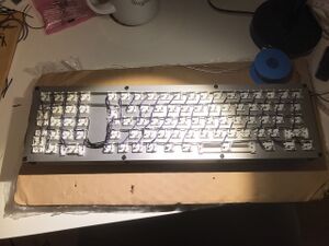
After finishing with the diodes, I began building the rows. This went slowly as I tried various techniques to quickly cut away enough of the insulation, in the right places, to wrap diode legs around, while leaving the row wire mostly covered. I started out stripping large sections of insulation at a time, cutting them to size, and feeding them back onto the wire, but this proved tedious, and by the end, I had settled on removing a smaller section to create clearance, then making approximate cuts to cover the wire between diodes without removing the small sections of insulation.
Most of the row wiring is in straight lines, but I curved the lower three wires to create a space for the controller between the main switch bank and the numeric keypad. Case thickness was one of my major concerns for handwiring, and I spent a substantial amount of time measuring, test fitting, and devising strategies to keep the necessary clearance inside the case to a minimum. One of my solutions for this was to ensure that the controller and its pin attachments could lie directly against the steel plates, without any switches or wiring above or below.
By evening, the rows were finished, and I added the columns, which went much more quickly. I took a similar approach to the rows for cutting insulation, but without the delicate diode legs involved, it was much easier to work one step at a time, wrapping wire around a switch post, test-fitting the section running to the next switch, cutting insulation, wrapping around the next post, and repeating until reaching the end. By the end of the day, the whole matrix was wired.
Friday: Connecting the Controller
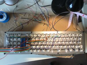
Intrigued by masterzen's tidy wiring, I decided that I, too, wanted to connect the matrix to the controller with a ribbon cable. This involved some tradeoffs. First, the wiring in ribbon cables is stranded, which is tedious to strip and solder by hand. These cables are not designed with hobby applications in mind, and they do best when crimped into purpose-built components. I was able to at least take advantage of one of these, by mounting the controller board onto a transition plug. The plastic housing of the plug dramatically increased the clearance required for the controller, though, and I was unsure whether the tall plug assembly, with a ribbon cable tidily extending out one side, would be easier to accommodate than loose wiring, but I decided to attempt it.
Using a box cutter, I separated the ribbon cable into bundles of five wires each, threading them under the matrix wires and selecting a staggered set of locations to terminate them on switch posts for the row and column connections. It was slow going, and I occasionally went astray and sliced into the insulation, but it worked out. Wrapping and soldering the exposed stranded wire got messy at times, though, and I am not especially proud of the solder joints that resulted. One of them, to the column containing 0 P ; / →, ended up periodically failing, requiring me to repair it several times in the coming years before eventually redoing it from scratch. I left the wires for the unused pins in a single loose bundle, in case any of the connected wires developed problems and needed to be replaced.
Extra care required with the fragile insulation and wire strands resulted in the controller wiring taking much of the day. After everything was soldered, I discovered a few bad or intermittent connections and began tracking down and repairing them, until deciding to sleep on the remaining few intractable problems.
Saturday: Programming and Debugging
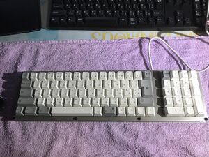
After addressing the remaining physical issues, I set about learning how to work with qmk to program and flash the controller firmware. This took a few tries to get right and eliminate bugs from the matrix definition, but by nighttime I had the firmware running properly, the switch plate flipped back over, and the keycaps installed. The controller on its transition plug hung loose in between the plates, and I ran a USB cable into the open frame to connect it to umaru. It looked very much unfinished, but it was functionally complete, and I could already tell it was going to be a joy to use.
Case Parts
I immediately switched over to the open-frame keyboard and revisited my plans for the rest of the enclosure with newfound confidence. In the interest of expediency, and deciding that I wanted that black glitter acrylic after all, I ate the high shipping costs and placed an order with Ponoko a few days after finishing the controller programming. The order was for four acrylic layers in total - a 4.5mm sheet in the middle, with a gap for the USB breakout board to sit in side of, two 3mm sheets surrounding it with screw holes for mounting the breakout board, and the 3mm black glitter top bezel piece.
At this point, I also decided on a screw and nut setup for the final assembly. My initial reluctance to do a sandwich case was out of distaste for the raw look that many DIY builders embrace, so I was especially concerned about screwing things together in a way that would be at least somewhat inconspicuous. My solution was to buy flat head hex screws in black, and a countersinking bit to make the screw heads flush with the bezel.